My plan for the final project is to build an RC car with an automatic gearbox, i.e. with the press of a button I would like to switch gears to adjust the speed of the car. For the purpose of the MVP, I sketched out my plan for the RC car and implemented the automated gearbox. With this out of the way, my next 3 big steps are building a chassis, an Ackermann steering for forward gears, and a wireless controller. The gearbox for me was the most challenging part since building gears that can switch orientation seemed non trivial. I used a driving ring mechanism that is detailed more below.
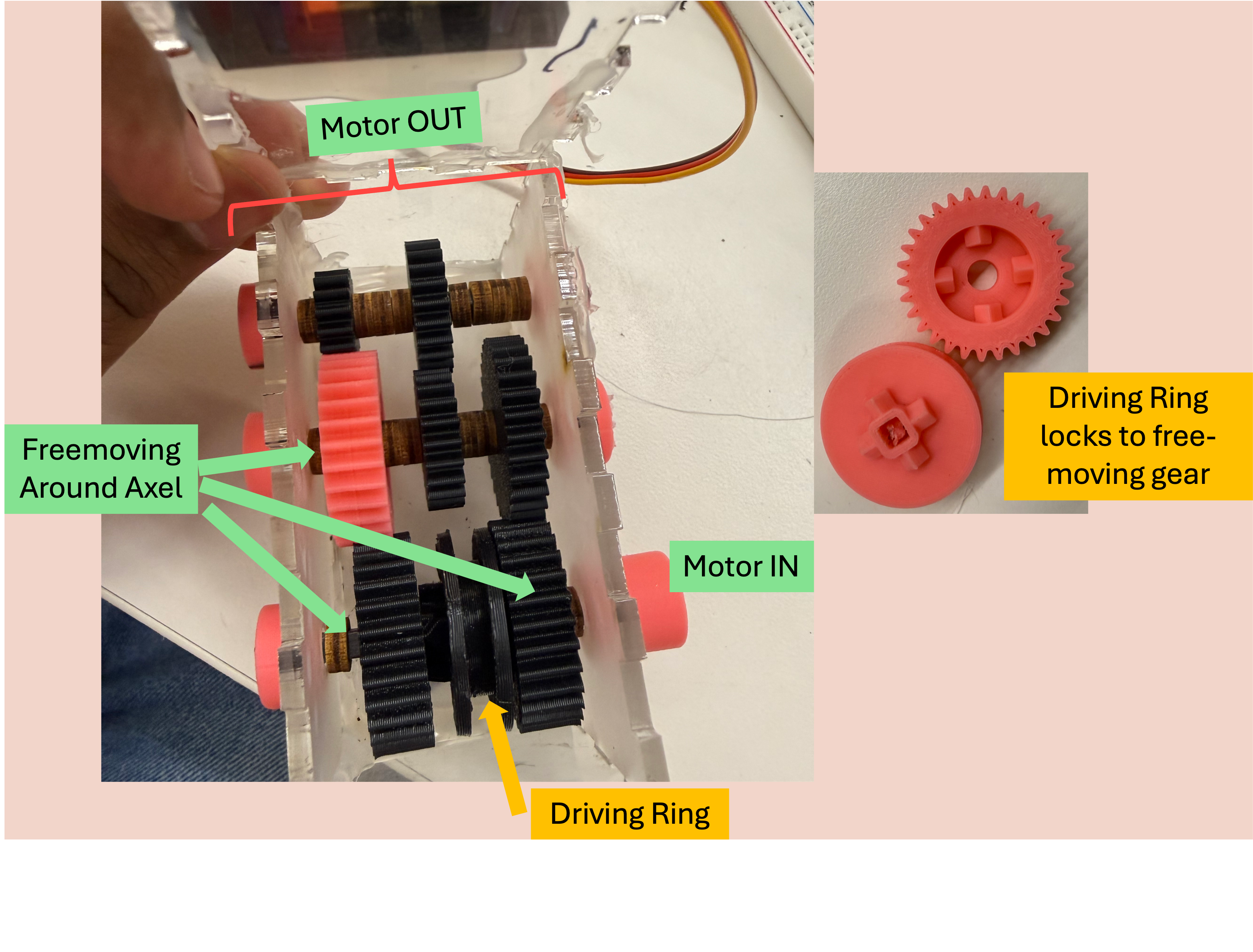
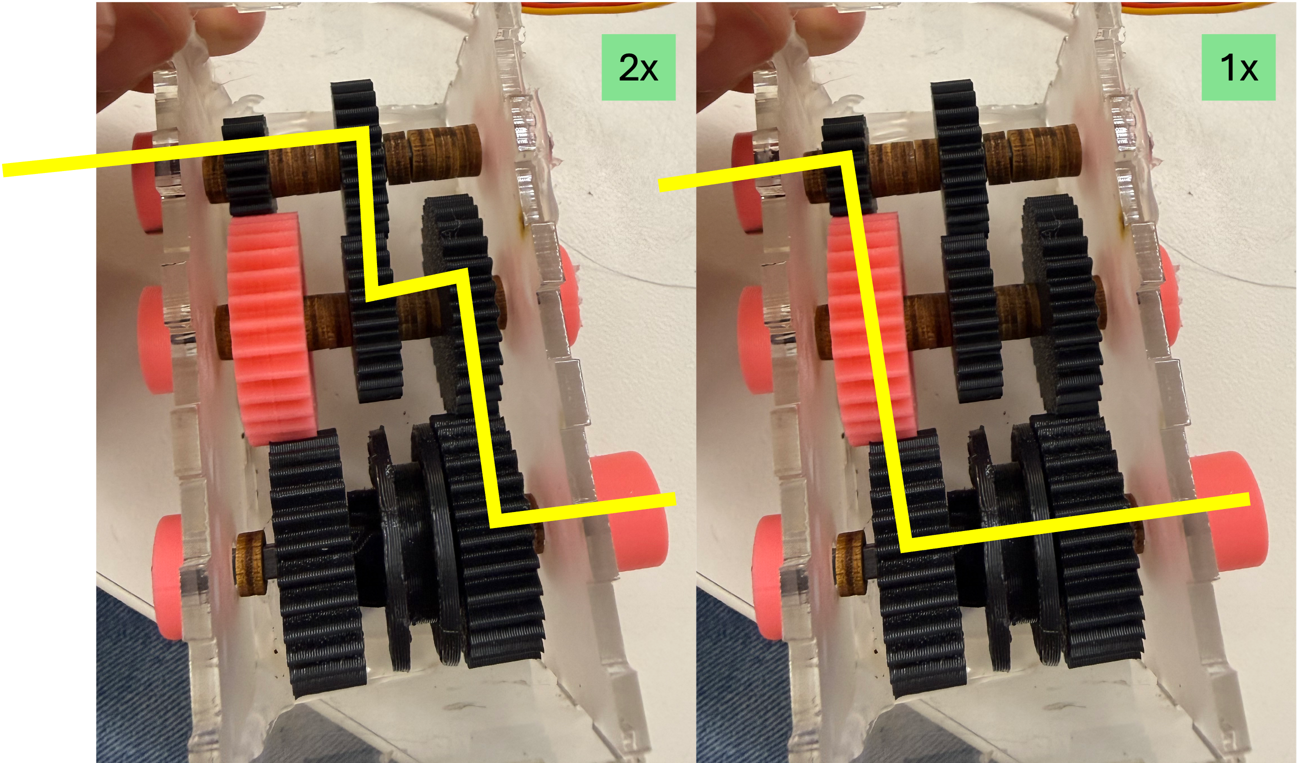
Driving Ring Mechanism
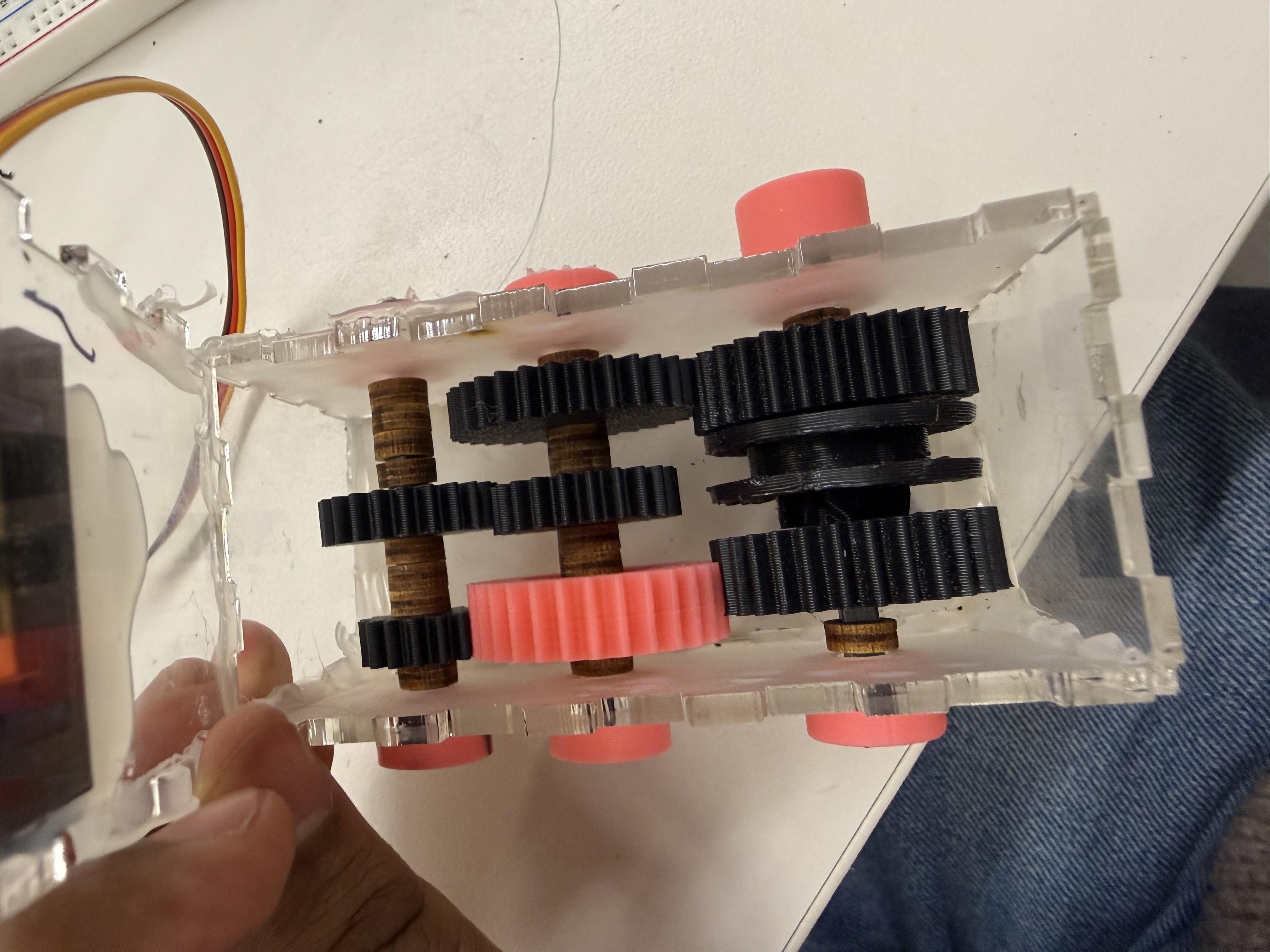
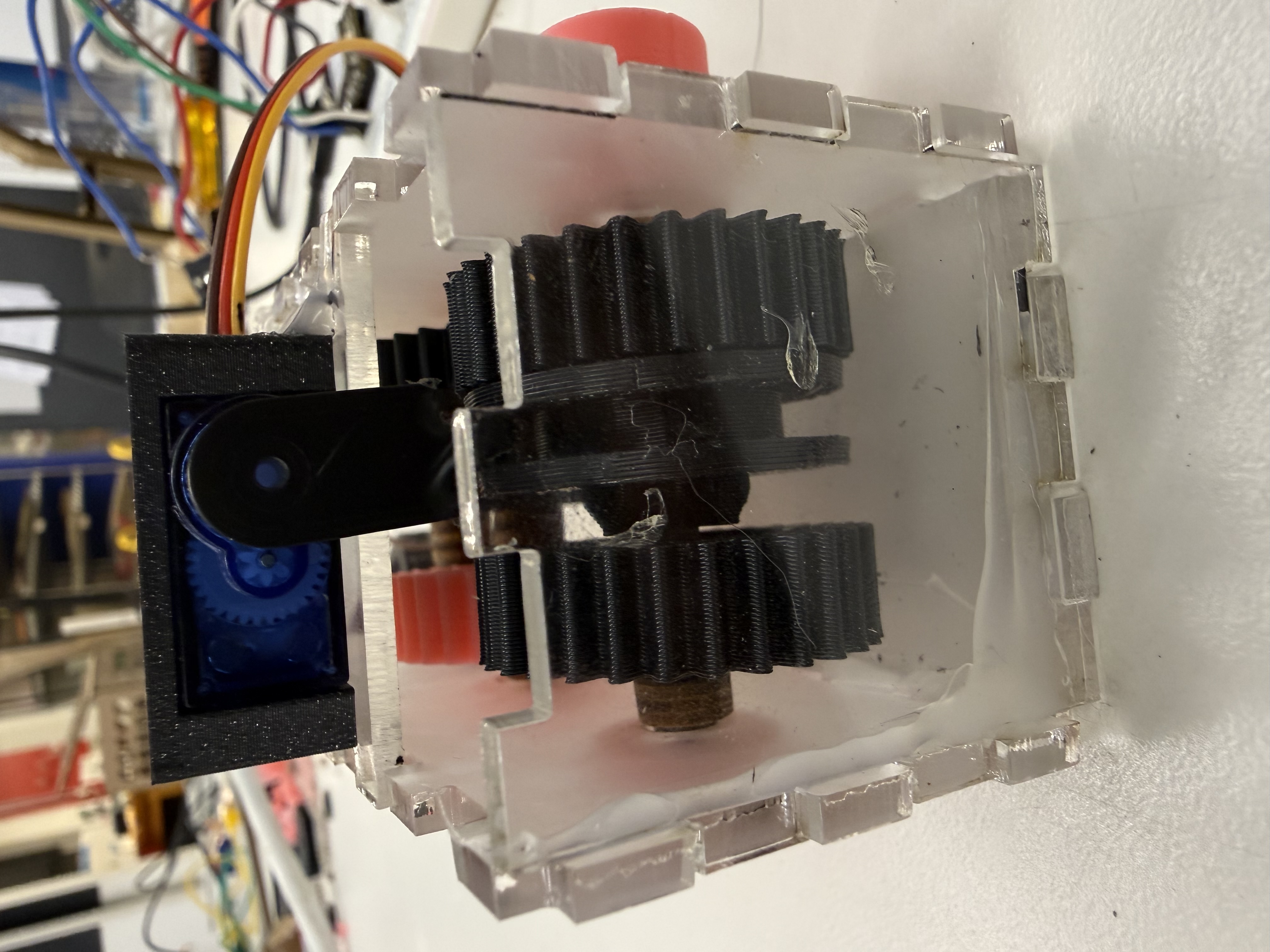
The most challenging aspect was this was implementing the driving ring mechanism. I tried to demonstrate it here with diagram. I am using 4mm rectangular carbon fiber dowels as axels. That might help understand why the circular holed gear free moves around the axel. We lock it in place to rotate by placing the driving ring in it. The triangle approaches ushers the driving ring in place, locking the 2 gears together. This is handled through a servo. The paths taken are explained with the lines at the bottom in image 2. In the left image, we see the path taken when locked to the gear closer to the motor (leading to 2x speed as we go from 3cm to 1.5cm spur) and in the other scenario it is the base speed since the gears go from 3->3; 2.25->2.25. I plan to attach the output to the rear axel using a bevel gear. The steering will exist for the front gears.
Other Implementation Details
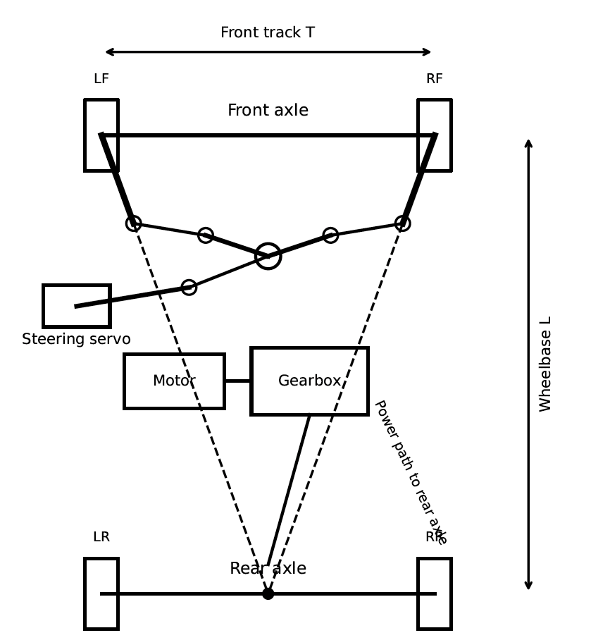
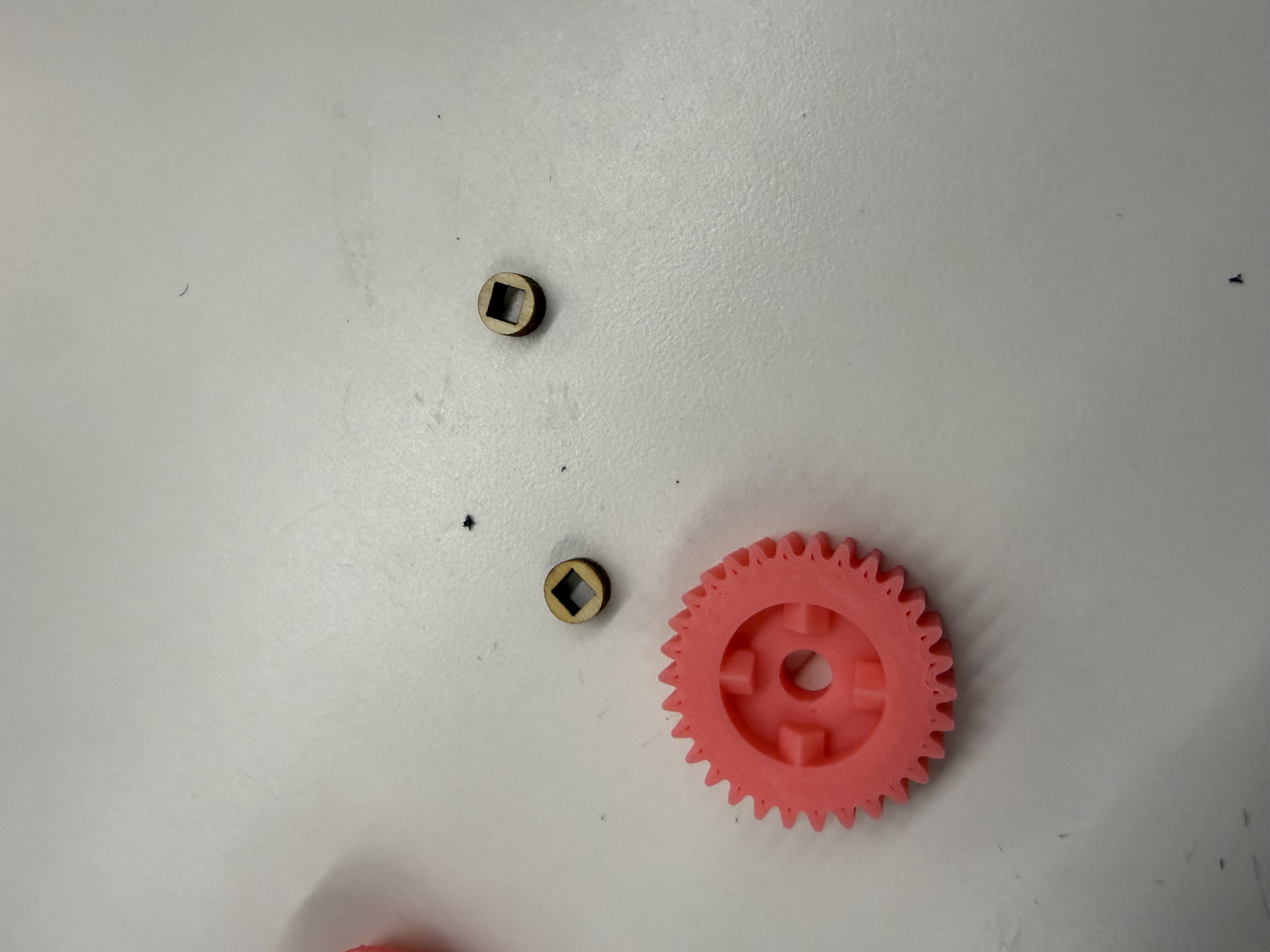
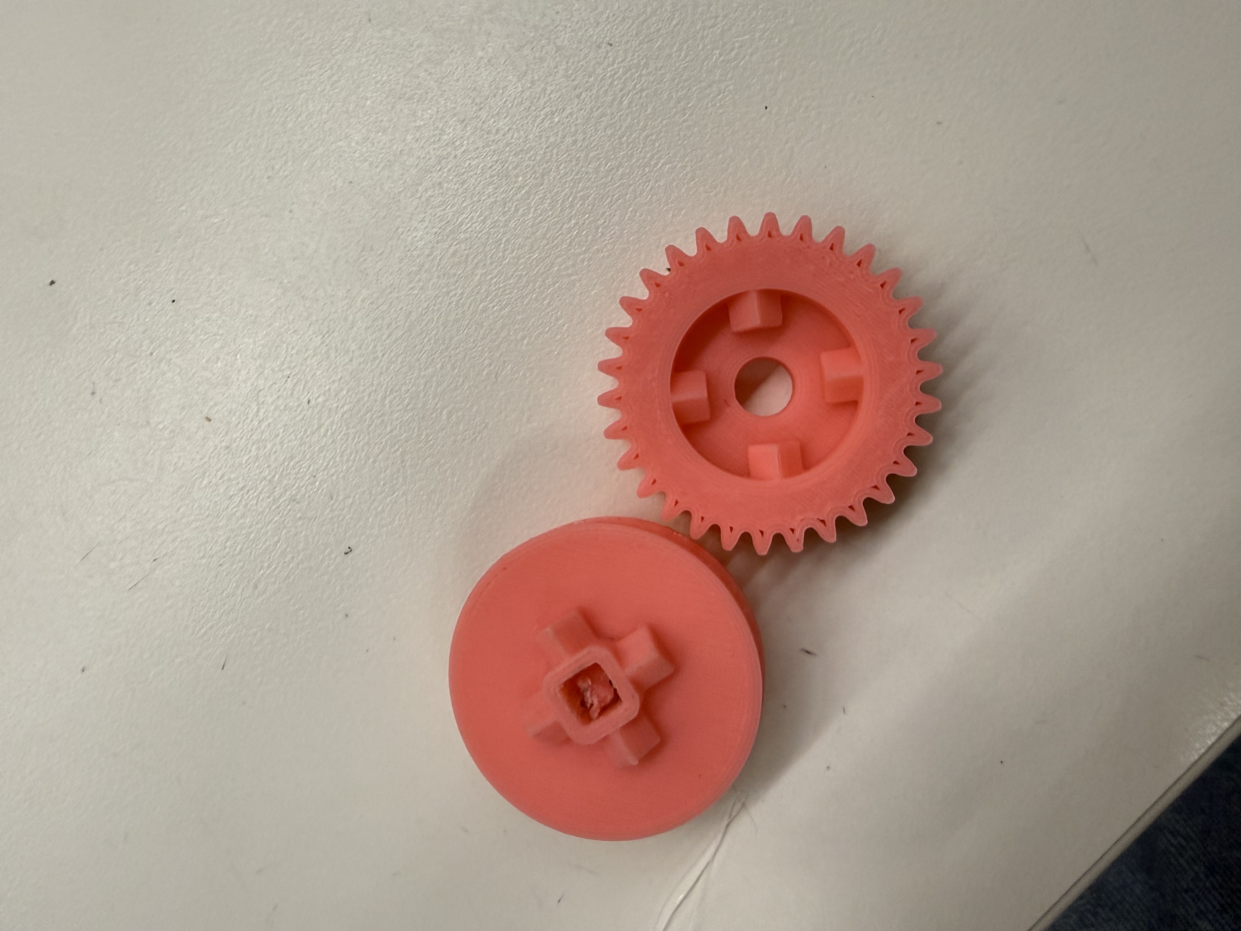
I 3-d printed the gears, the motor to axel connector and tight-fit nuts for axel ends. The spacers inside the gearbox were laser cut, so was the box. Currently the housing for the DC motor is just the base, that will fit into the chassis alongside the gearbox, I will build housing to secure the motor from the top too. Currently there is some friction in the 2x speed path that leads to the gears slipping, will fix that by reinforcing the connections and cleaning the 3d printed gears. The chassis should be pretty easy to design once I nail the Ackermann steering. Here is the general steering plan here in this diagram.
Steering plan diagram (expand)
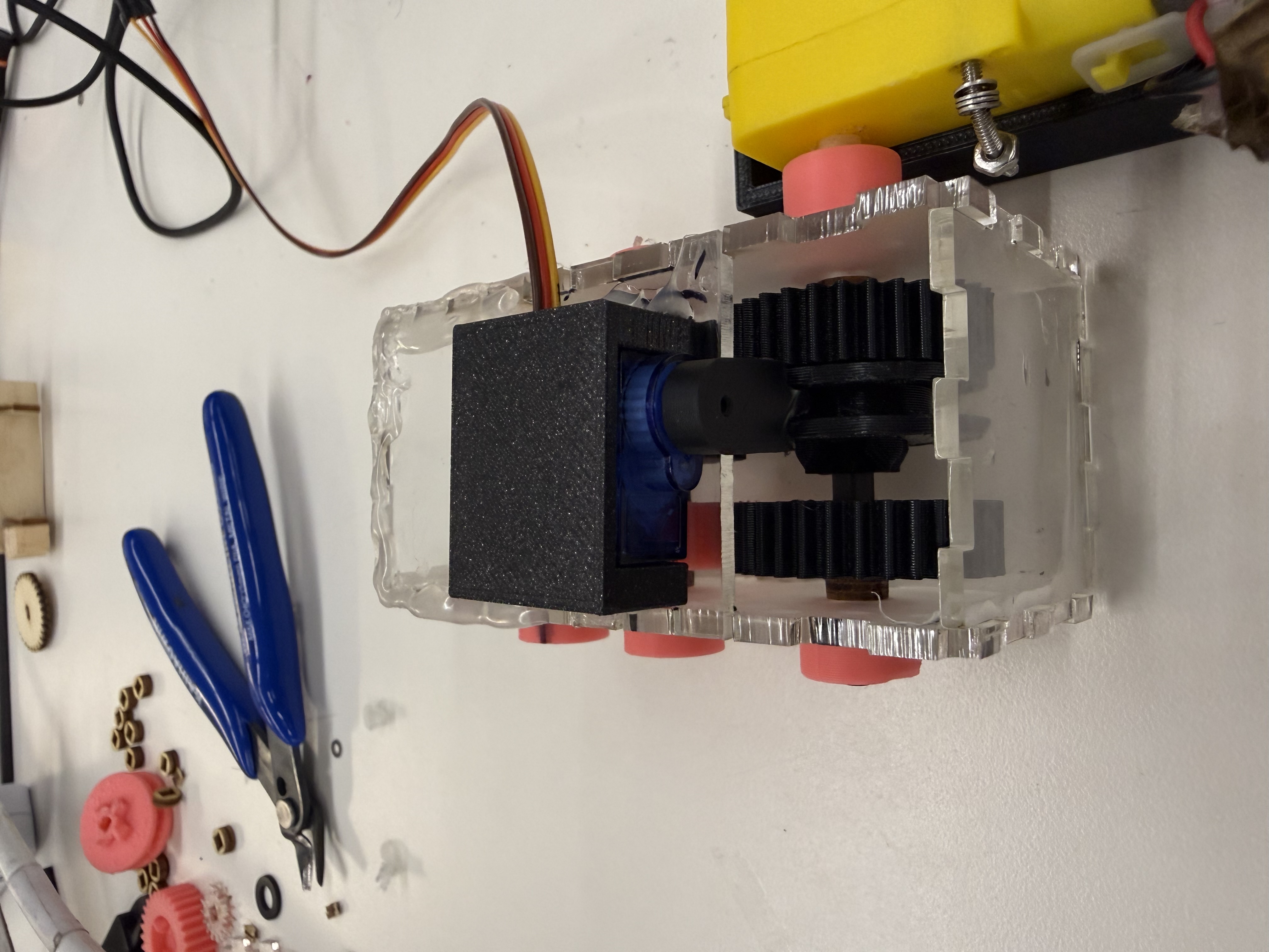
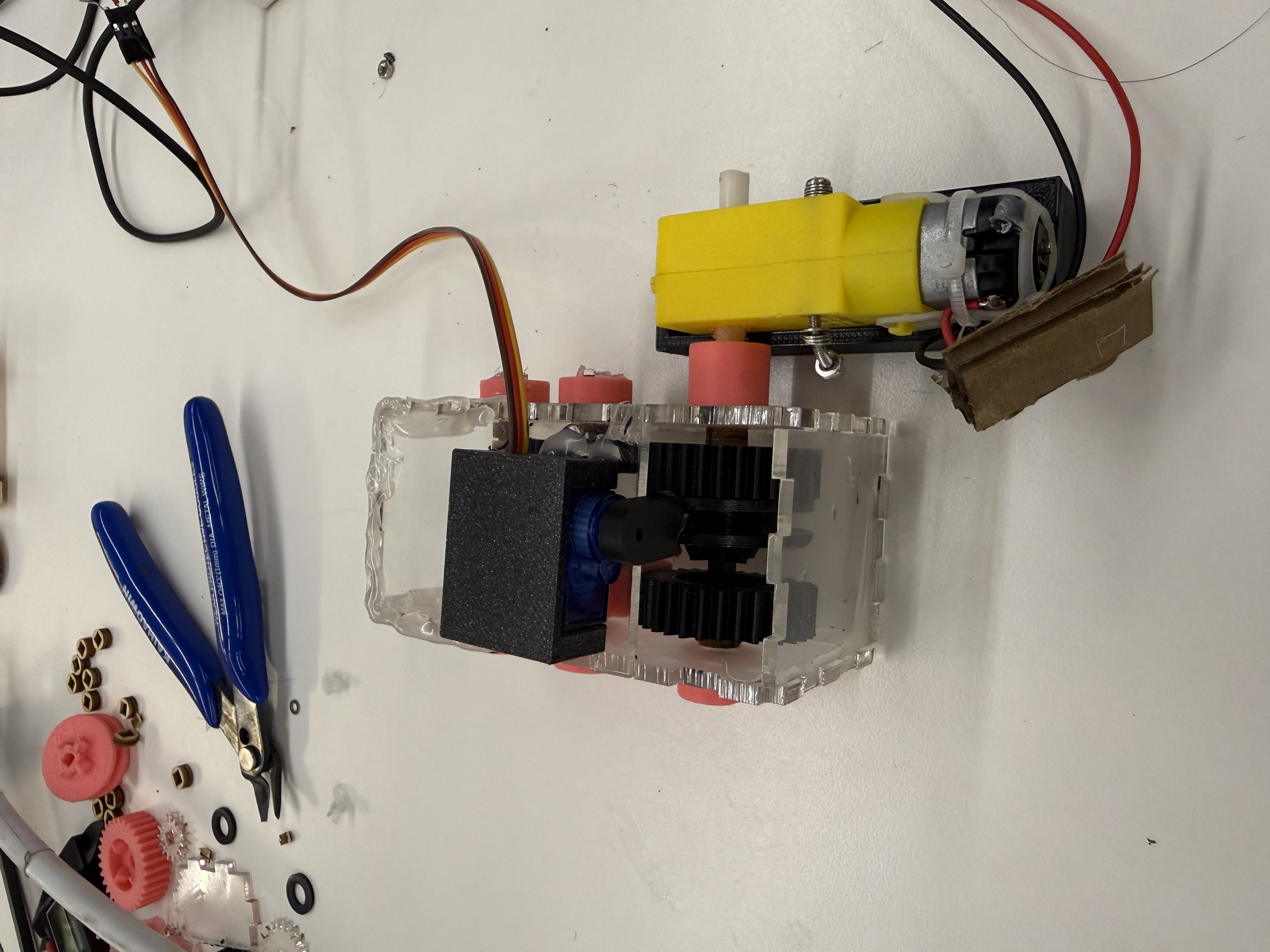
Photo Gallery
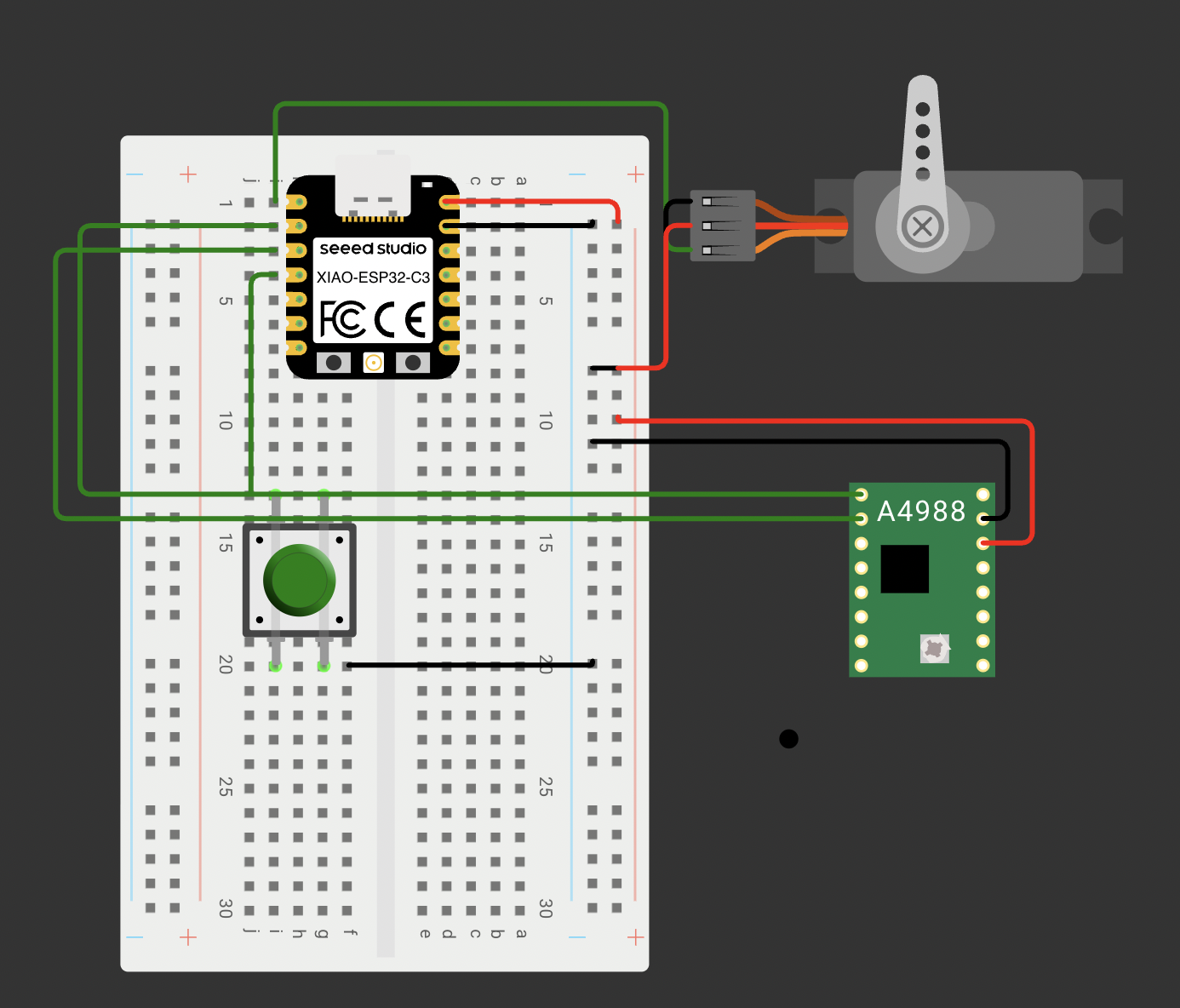
Circuit Diagram and Code
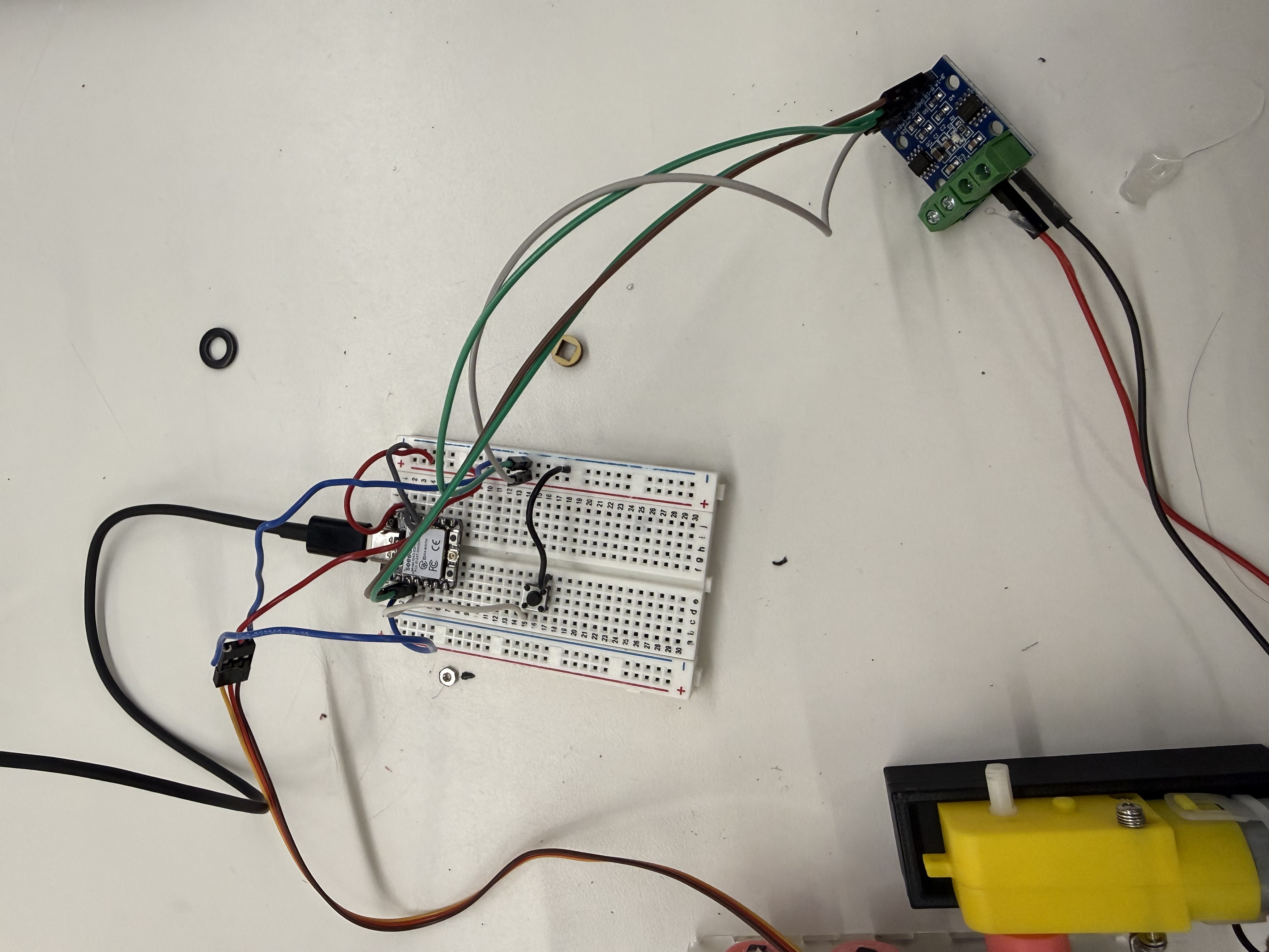
The circuit simply plays connects the servo and DC motor with a push button. By default, the DC motor drived the gearbox forward at 1x speed. When we press the button, the motor slows down, the servo toggles the driving ring to the other gear switching to 2x speed. Everytime we next press the button, the process repeats toggling between 1x and 2x speed. You can expand the code here.